What is Pump Cavitation, and How Do I Avoid It?
And Four Ways to Prevent It
When asking, 'What is cavitation?', it is important to understand that cavitation is a phenomenon that occurs within pumping systems, characterized by the formation and implosion of vapor bubbles due to pressure variations. These vapor bubbles can cause significant damage to metal components. To prevent cavitation, it is crucial to match pump specifications to the fluid and system requirements.
And Four Ways to Prevent It
Cavitation in pumps is the rapid creation and subsequent collapse of air bubbles in a fluid.
Bubbles might not seem very powerful, but the types of bubbles in pumping systems are nothing like the ones you make by waving a wand around with little kids. Tiny cavitation bubbles created by changes in pressure inside pumps collapse and generate shock waves that occur over and over and the repeated shocks erode the components.
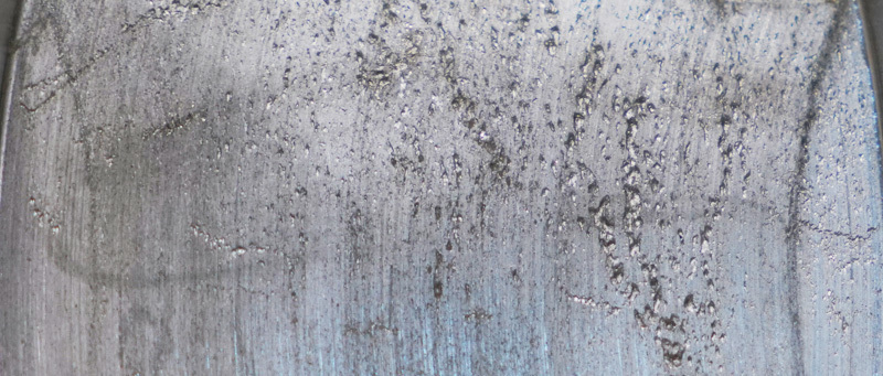
In many cases, the force of cavitation is strong enough to pit metal components of the pump, like the impeller, and damage pump seals.
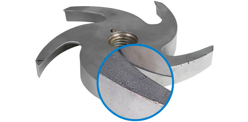
Why does Pump cavitation occur?
Pumps are designed to work with a full-flowing water supply, but in some cases, a flooded inlet is insufficient to maintain the pressure required to prevent cavitation. The pump's inlet, or suction side, is the point of lowest pressure in a given pump. Maintaining adequate inlet pressure is crucial to prevent cavitation, as manufacturers assess it to establish safe operational limits for pumps. For positive displacement pumps, the lowest pressure occurs just prior to rotor meshing; for centrifugal pumps, lowest pressure is near the eye of the impeller.
Cavitation is possible in all pump types and since its principles are essentially the same, we will focus on centrifugal pumps. The eye is where fluid is drawn into the impeller and where the rotation of the impeller begins to act on the fluid. When pressure acting on the liquid (Net Positive Suction Head Available) is too low, bubbles form, and as the liquid accelerates because of impeller rotation, pressure increases and the bubbles collapse.
Under normal atmospheric pressure conditions, fluids have predictable vapor pressure. As the pressure inside the pump falls below the liquid’s vapor pressure, bubbles form. The bubbles collapse when they reach areas of the liquid where the pressure is above the vapor pressure. In the case of cavitation, this formation and collapse is both rapid and violent. Disrupted or poorly executed processing lines can cause suction or static pressure to fall, which leads to cavitation.
Poor pump inlet condition
Disruptions to flow may have several causes, from system design to component degradation. Common causes of flow disruption that result in cavitation:
- Excessively long inlet piping
- Higher than expected fluid viscosity
- Clogged inlet
- Clogged filters and strainers
- Restricted or collapsed inlet hoses
- Poorly specified pump
Disruptions in a fluid flow system can lead to cavitation, where pressure drops cause vapor bubbles to form and collapse, damaging pump components.
Discharge cavitation
Some fluid circulates inside the pump at extremely high discharge pressure instead of discharging. An improperly adjusted discharge valve can lead to cavitation by causing suction recirculation and pressure fluctuations. Fluid trapped between the impeller and housing at very high velocity causes a pressure drop, creating the same conditions as for suction cavitation.
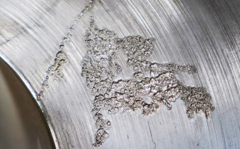
How to Recognize Cavitation Damage
Cavitation sounds like marbles or gravel circulating through the pump, pipes, or hoses. The collapsing cavitation bubbles emit significant energy, including sound and shockwaves, which can lead to various technological challenges. The effects of prolonged cavitation are visible on the pump impeller and other components.
Typical indications of cavitation:
- Noise
- Vibration
- Seal/bearing failure
- Impeller erosion
- Higher than usual power consumption
How to prevent pump cavitation
Start by identifying the cause of the pressure drop. In many cases moving the pump closer to the fluid source and removing as many bends and valves as possible corrects the problem because each component causes additional pressure drop. When suction lift is too high to maintain pressure, move the pump closer to the fluid source or move the fluid source closer to the pump.
Cavitation can lead to severe erosion of pump components, including seals and bearings, due to the formation and implosion of vapor bubbles around the pump impeller.
Enlarging suction lines can also be effective. In some obvious cases, a blockage occurs in piping or hoses near the pump. Clear those blockages to resolve the issue Clean suction lines by clearing debris. Avoid blowing the debris back toward the fluid source because it’s likely to create a blockage again.
Don’t exceed your pump manufacturer’s performance guidelines. Pump curves tell you how much net positive suction head the pump requires, so check your pump’s performance curve to ensure it has the right specifications for your application.
A Guide to Choosing the Right Pump for Hygienic Applications
This guide is intended for engineers, production managers, or anyone concerned with proper pump selection for pharmaceutical, biotechnology, and other ultra-clean applications.
1. Pump selection
The best way to prevent cavitation is to select the right pump for the application. Cavitation increases as the pump head falls or capacity increases, so selecting the correct pump to maintain a positive margin of NPSHa above NPSHr is the best first move.
NPHS at the inlet depends on atmospheric pressure, friction losses in the suction piping, and flow velocity. A good rule of thumb is for pressure at the pump inlet to be 10% greater than the pump's specified NPSHr. For example, if NPSHr is 10 feet, NPSHa should be at least 11 feet.
When purchasing new pumps, consider the pump design and always question whether it meets the Net Positive Suction Head (NPSH) requirements.
How to increase net positive suction head available
2. Addressing discharge cavitation
Discharge cavitation occurs when the pressure at the discharge end of the pump is too high. High discharge pressure limits the fluid flow of the pump, causing high-velocity fluid to recirculate between the pump impeller and housing, causing cavitation.
Common causes of discharge cavitation
- Clogged filters
- Pipe blockages
- Poor piping design
Preventing discharge cavitation
- Keep reducers as close to the pump as possible.
- Install the control valve, if needed, on the discharge side--never on the suction side.
- Avoid pockets where air or vapors can accumulate.
| Cause | Effect |
|---|---|
| NPHSa falls below NPSHr | Cavitation due to decreased pressure |
| Restricted discharge flow | Cavitation due to low flow condition |
| Leaks in packing, piping, o-rings, seals | Cavitation due to air aspiration |
| Restricted suction flow: sharp elbows, clogged filters or strainers | Cavitation due to turbulence |
3. Routine pump maintenance
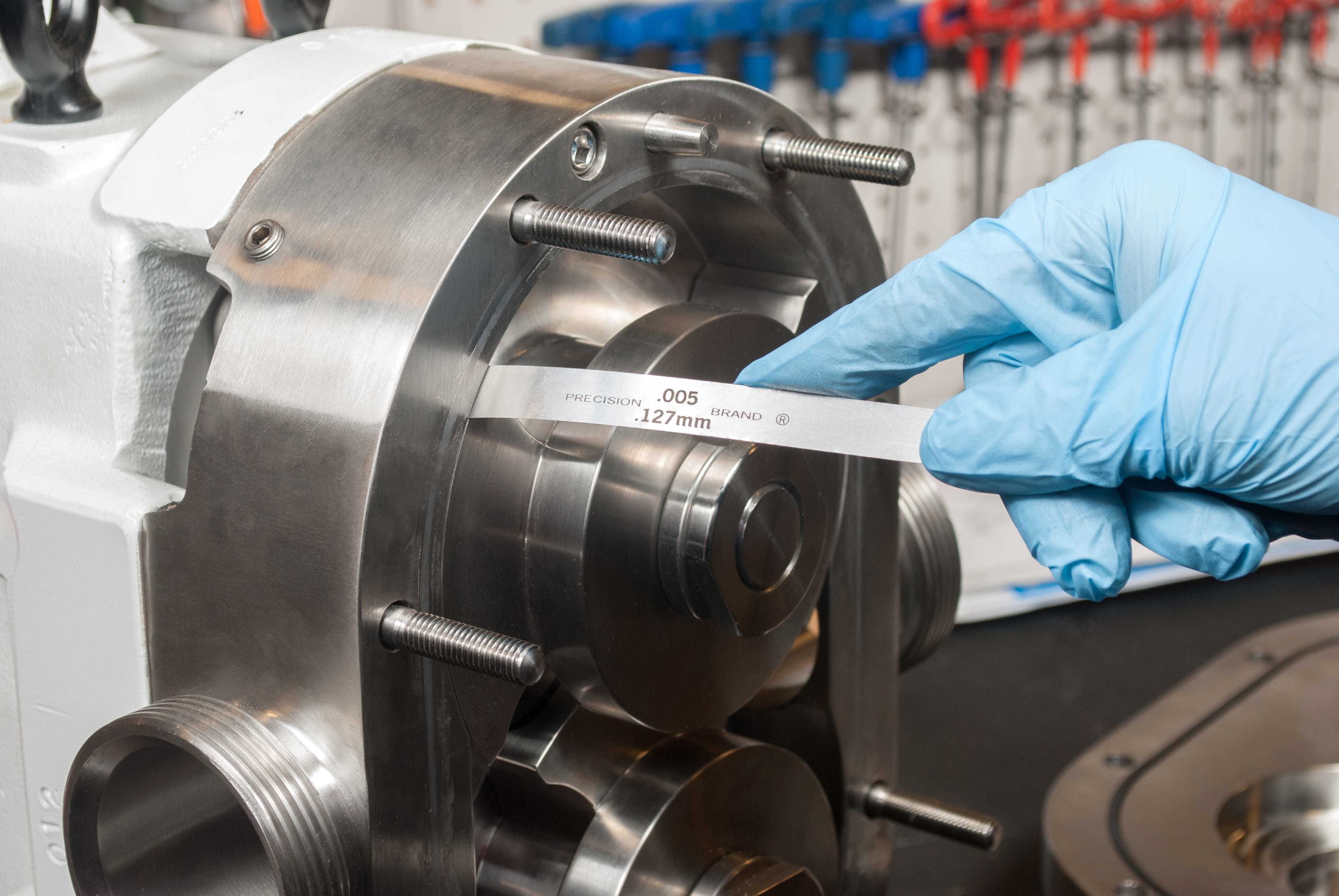
After proper pump selection, regular maintenance is the best way to avoid cavitation.
Routine maintenance extends pump life and consistent performance.
- Check filters and strainers. Dirty or blocked filters and strainers generate pressure buildup inside the pump. Setting a maintenance schedule ensures that systems are in place to keep the pump system flowing at capacity.
- Assess the entire pump system design: ensure that the optimum flow rate is available through pump elevation and downward flow when possible.
- Evaluate the curve. Consider the job pressure demands and then the pump data to see if it fits the application. From there, determine if the pump fits the needed flow rate.
- Monitor pressure sensing equipment.
- Look for cracks or collapsed piping/hoses that will disrupt the system.
4. Proper Installation
The best ounce of cavitation prevention is pump selection and system design for maintaining pressure and flow. The goal of installation is therefore to maintain net positive suction head available (NPSHa) at greater than net positive suction head required (NPSHr) by considering four key variables:
- Pump location
- Suction pipe length and diameter
- Suction lift, or the vertical distance from water source to pump inlet
- Friction loss
Proper installation can prevent the formation of cavitation bubbles, which are known to cause high-energy shock waves and erosion effects around pump impellers.
Pump location
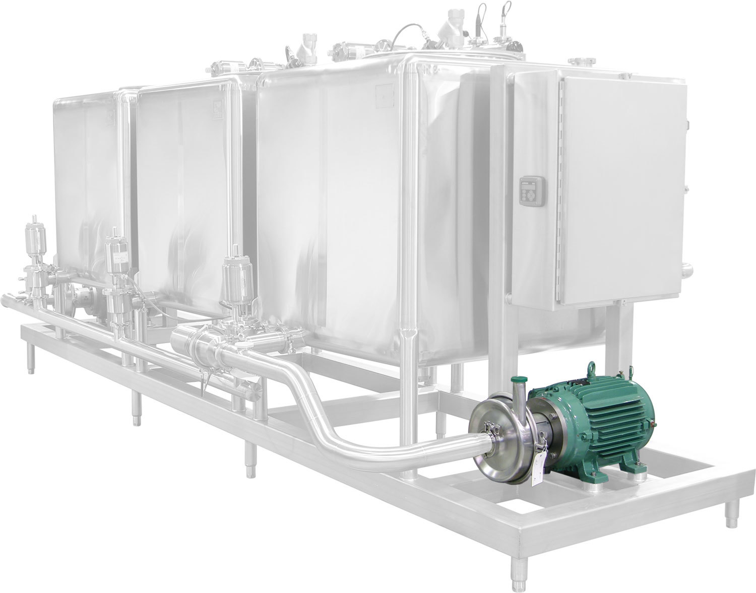
Physically install the pump so the water flows into the pump suction inlet smoothly. Make sure that the suction lines leading to the inlet of the pump are adequately sloped to ensure that the pump housing is flooded.
Placing the pump at a point that is lower than the water level in the tank from which it pumps, for example, uses the force of gravity to maintain flooded suction, which in many cases prevents cavitation.
Pumps, and especially centrifugal pumps, work most efficiently when the fluid travels in a smooth, laminar flow, and turbulence of any kind reduces pump efficiency, so positioning the pump as close as possible to the fluid source makes sense.
In general, you want 12 cm of straight pipe for every centimeter of pump suction diameter. To maintain laminar flow, connect 5-10 pipe diameters of straight piping to the pump inlet. Do not include elbows, reducers, valves, or strainers within the final length of pipework. Connecting an elbow directly to the pump flange, for example, draws fluid towards the outer curve of the elbow instead of directly into the eye of the impeller.
Also, the piping arrangement must not cause strain on the pump casing, so pumps can never support the piping for suction or discharge. Use hangers and supports instead.
Suction-side piping is commonly one or two sizes larger than the pump inlet — never smaller than the pump's inlet.
Larger pipework requires a reducer before the pump inlet and must be designed carefully to avoid turbulence and creation of air pockets at the inlet.
In general, keep suction pipe velocities below 2 m/s. Higher velocities can create more friction and more noise.
Suction lift, or the vertical distance from water source to pump inlet
Suction lift can place higher than necessary energy demands on pumps, increase turbulence, and decrease NPSHa.
The solution is to install the pump below the water level of the supply tank and meet standards for piping design.
Suction Lift Examples

Friction loss
As fluids pass through a pipe, friction between the fluid and the inside surface of the pipe causes turbulence, which slows the fluid and results in a pressure drop. Pipe length, diameter, and flow rate all affect friction loss.
Maintaining adequate static pressure is crucial in preventing cavitation. A drop in static pressure, particularly as water interacts with pump components, can lead to vapor formation and damaging bubbles, thus emphasizing the importance of maintaining adequate static pressure throughout the system to avoid mechanical failures.
Good piping layouts prevent cavitation by helping to maintain constant velocity. Obstructions in piping layouts affect flow velocity, which changes fluid pressure, which can cause cavitation.
Standards for good piping design
- Ten diameters of pipe between the pump suction and the first elbow.
- The upstream conditions should have a minimum straight run of ten pipe diameters to provide uniform flow to the suction inlet.
- Keep reducers as close to the pump as straight-run requirements allow. Use eccentric reducers, flat side up, on the majority of pump suction lines.
- Use long-radius elbows; minimize the number of elbows.
Troubleshooting checklist
- Is the pump installed too high above the fluid source?
- Is suction pipe diameter too small?
- Is the suction pipe too long?
- Are there too many fittings on the suction pipe?
- Is the pump running too fast?
- Is the suction line to the pump sloped properly?
While it's true that some cavitation can have positive purposes, such as for surgical equipment sterilization or to break down pollutants in water systems, it's not something you want in your processing system, so time spent preventing cavitation is time well spent.
Next Steps
When your pump, pipe, or hose sounds like marbles or gravel are circulating, you're witnessing cavitation and need to take immediate action or risk severe damage to components. When cavitation does occur, you need a trusted partner that can diagnose the cause, provide a long-term solution, and repair or replace parts that are damaged.
CSI's pump service and maintenance program is designed to take the irritation and guesswork out of dealing with pump cavitation. Each audit and repair that CSI completes include an evaluation by an OEM-trained pump technician, a report on the findings, and all the materials required to perform the service.
Call us today to schedule your next system audit or pump repair!
ABOUT CSI
Central States Industrial Equipment (CSI) is a leader in distribution of hygienic pipe, valves, fittings, pumps, heat exchangers, and MRO supplies for hygienic industrial processors, with four distribution facilities across the U.S. CSI also provides detail design and execution for hygienic process systems in the food, dairy, beverage, pharmaceutical, biotechnology, and personal care industries. Specializing in process piping, system start-ups, and cleaning systems, CSI leverages technology, intellectual property, and industry expertise to deliver solutions to processing problems. More information can be found at www.csidesigns.com.
